DESIGN OF PRE-ENGINEERED BUILDINGS (PEB)
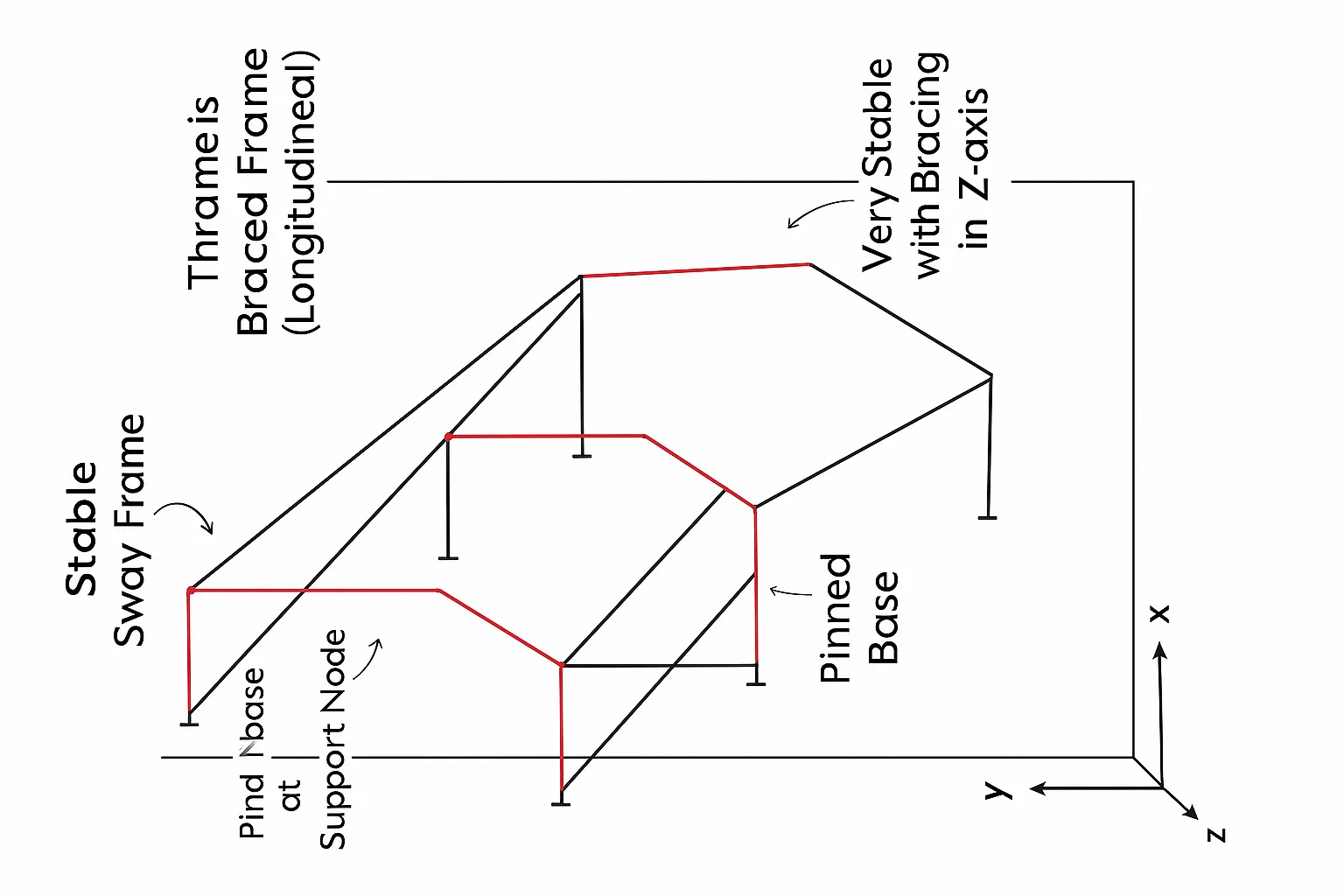
- DESIGN OF PRE-ENGINEERED BUILDINGS (PEB), PEBs, as compared to conventional steel buildings, are made from the built-up sections, i.e., made of plates generally welded to each other to create the required section.
- The structural engineer decides the width of flanges with their thickness, the sizing of the web, and the size of welds. The tapering of the structural members can be carried out as per the bending moment diagram (B.M.D) of the steel portal frame. This decides the strength, stability & economy of the section.
- IS 800-2007, General Construction in Steel – Code of Practice
- IS 875-P1, Code of Practice for Dead Loads for Buildings & Structures
- IS 875-P2, Code of Practice for Live Loads for Buildings & Structures
- IS 875-P3-2015, Code of Practice for Wind Loads for Buildings & Structures
- IS 875-P4, Code of Practice for Snow Loads for Buildings & Structures
- IS 875-P5, Code of Practice for Special Loads & Combinations
- IS 801, Code of Practice for Use of Cold-Formed Light Gauge Steel Structural Members in General Building Construction
- IS 811, Specification for Cold Formed Light Gauge Structural Steel Section
- IS 4923, Hollow Steel Sections for Structural Use
- IS 808, 2021, Hot Rolled Beam Sections, Column, Channel & Angle Sections
– Dimensions & Properties
{ Clause-by-Clause Instructions Given By The Code of Practices Shall Be Understood To Get the Application Part of Them }
FRAMEWORK FOR DESIGN
(1) Planning of industrial layout based on client inputs
(2) Input from vendors for cranes can be assumed
(3) Skeletal Modeling and Estimation of Loading (primary) and Load Combinations (as per code)
(4) Analysis & Design in software with given parameters and design commands (instructions)
(5) Structural Optimization
Steps: 1 to 3 → Pre-Processing Part
→ Includes member property definition, material property specification, and support conditions
Steps: 4 to 5 → Post-processing Part
→ Includes: static & dynamic definitions → method of analysis → design parameters → lx, ly, lz, beam 1-way stiffness, etc. in StaadPro software
MAJOR LOADS IN INDUSTRIAL BUILDINGS
(A) Dead Load (DL)
- self-weight of structure, its connections & other accessories
- These include: roof sheeting, purlins, sag rods, fly braces, bracings, etc.
- column dead loads including side wall sheeting, girts, sag rods, fly braces, bracings, eave gutter, etc.
- mezzanine floor decking slab
- crane rail weight, self-weight of the gantry girder
(2) Live Load (LL)
- inaccessible roof live load = 750 N/m² (IS 875-P2)
= 5 kN/m² (MBMA) - Due to water in the eave gutter
- mezzanine floor live load, depending on the occupancy
(3) Collateral Load (CLL)
- Additional dead loads hung from the building: sprinkler systems, drop ceilings, HVAC equipment, lighting fixtures, etc.
(4) Wind Load (WL) – IS 875 (P3)
→ Basic wind speed (Vb) based on the location of the building
→ Wind pressure (Pz) = 0.6 Vz² kN/m² (based on building dimensions & roof slope)
- External Pressure:– Occurs on the exterior of the building. Coefficients to be calculated as per the tables given in IS 875–P3
- Internal Pressure:– Occurs inside the building and tries to uplift the structure or blow the side walls/frames → Negative Pressure
Coefficients to be determined based on the % of opening in the building as the wind can enter through them inside.
(5) Seismic Load (EQ) – IS 1893 (P4) & (P1)
- In software, give the definition of EQ loads and generate EQ cases as the initial load cases in StaadPro.
- Only dead load is considered for EQ loads. No live load to be considered for PEB buildings to generate EQ load to be taken for floors.
- Appropriately 25% or 50% of the live load
- Ah=ZISa2RgA_h = \dfrac{Z I S_a}{2 R g}Ah=2RgZISa
- Vb=AhWV_b = A_h WVb=AhW
- Estimate the time period in both directions
(6) CRANE LOAD (CL) – Vendor, IS 875-P2, IS 800-2007
- In StaadPro software, the estimation of joint weight is required if they exist in addition to self-weight
- Based on the capacity of the Gantry Girder, the supports at the base are to be decided
- wt. of crab trolley, lifting weight to be taken from client/vendor
- IS 875-P2, IS 800-2007
- Refer to Moving Load Analysis and correspondingly Load Combinations for the design of Gantry Girder & Column Brackets / Stepped Column
- Impact factor of 1.25 for vertical loads. Correspondingly, horizontal & longitudinal thrust forces are to be estimated



1 comment