Analysis and Design of G+5 Hostel Building

Table of Contents
INTRODUCTION
Analysis and Design of G+5 Hostel Building The arrangement and connections of different parts or elements that comprise a complex entity, whether natural (such as living things or chemical compounds) or man-made (such as buildings or machines), are referred to as a structure. Every construction in civil engineering is designed and carried out with consideration for its intended use, the availability of materials, cost, and aesthetic appeal.
In ancient times, humans sought shelter from environmental hazards by living in caves, under trees, or atop them. As humanity evolved, so did construction techniques—progressing from stone caves to timber shelters, mud dwellings, and eventually to brick concrete, and steel structures. Simply put, a building is an enclosed space with walls and a roof, fixed to a particular location. The advancement of building construction reflects the social development of a nation.
Innovative techniques are continually developed and refined to construct buildings efficiently, cost-effectively, and in line with community needs. Based on survey data, architects prepare detailed plans and elevations for buildings. Structural engineers then apply various design methodologies—such as the Working Stress Method (WSM), Ultimate Load Method (ULM), and Limit State Method (LSM)—to ensure that the structure is safe and functional. With the help of support staff like draftsmen, they finalize the design details, which are subsequently implemented by site engineers.
The design of any Reinforced Concrete Structure (R.C.C.) member involves the following key objectives:
- Determining the dimensions of structural members and the required reinforcement.
- Ensuring the selected section can perform safely and efficiently throughout the structure’s lifespan.
Reinforced concrete members can be designed using one of the following approaches:
- Theoretical calculations based on established theories and procedures outlined in applicable codes of practice.
- Experimental analysis on models or full-scale structures or elements.
For common structures, theoretical methods are typically used. The primary methods for designing reinforced concrete structures include:
- Modular Ratio Method (Working Stress Method)
- Load Factor Method (Ultimate Load Method)
- Limit State Method
(i) Modular Ratio Method or Working Stress Method
This is one of the earliest design approaches, rooted in elastic theory. It assumes that both concrete and steel behave elastically and follow Hooke’s law, meaning stress is directly proportional to strain until failure. Based on this theory and the assumption of a perfect bond between steel and concrete, permissible stress values are determined. Safety factors are applied to material strengths to account for uncertainties in manufacturing. For example, IS 456 specifies a safety factor of 3 for bending compressive stresses in concrete and 1.78 for the yield/proof strength of steel.
Limitations of the Working Stress Method:
- It assumes concrete behaves elastically, which is inaccurate, as concrete exhibits inelastic behavior even under low-stress levels.
- Safety factors are applied only to stresses, not to loads, leading to an unclear safety margin for load-related failures.
- It neglects time-dependent factors like shrinkage and creep.
- This method produces uneconomical sections and ignores collapse conditions.
While simple and reliable, this method is generally used only when the Limit State Method cannot be applied, as per IS 456: 2000.
(ii) Load Factor Method or Ultimate Load Method
In this approach, the structure is designed based on ultimate or collapse loads, which are derived by applying load factors to working loads. The method uses the actual stress-strain relationships of steel and concrete and considers their plastic behavior.
The load factor is defined as: Load Factor = Collapse Load / Working Load
Advantages:
- It accounts for the non-linear behavior of concrete, making it more realistic than the Working Stress Method.
- It provides a clear margin of safety in terms of loads.
- Sections designed using this method are thinner and require less reinforcement, making the method economical.
Limitations:
- It results in thin sections prone to excessive deformation and cracking, compromising serviceability.
- It does not include safety factors for material stresses.
Due to these limitations, the Limit State Method has largely replaced this approach.
(iii) Limit State Method :
The Limit State Method is considered the most rational design approach. It integrates the concepts of safety at ultimate loads (as in the Ultimate Load Method) and serviceability at working loads (as in the Working Stress Method). A limit state represents the acceptable threshold of safety and serviceability before failure occurs.
Types of Limit States:
- Limit State of CollapseThis involves the structural strength under various conditions:
- Flexure Shear and bond
- Torsion
- Compression
- Limit State of Serviceability: This relates to usability criteria such as:
- Deflection
- Cracking
- Vibration
The Limit State Method balances strength and serviceability requirements, making it the most widely adopted design approach today.
ABOUT THE PROJECT:
The project consists of Hostel Building G+5. The analysis and design of a multi-storied (G+5) hostel building using ETABS (22.1) and AutoCAD is used for drafting purposes. The building was designed in compliance with IS Codes: IS 456:2000, IS 1893:2016, IS 875, IS 13920:2016, and SP-16.
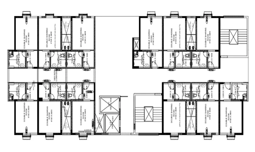
Plan and Elevation:
The project consists of 60 double-shared rooms with a total occupancy of 120 people with a floor height of 3.15m.
Description of Building
| Utility of Building | Hostel Building |
| Structure Type | Special Moment Resisting Frame |
| Number of Stories | 6 |
| Slabs | One way slab, Two-way slab, and cantilever slab |
| Footing | Isolated and Combined |
| Grade of concrete | M30 |
| Grade of Steel for main bars | Fe 550 |
| Grade of Steel for stirrups | Fe415 |
Design Codes
| Preliminary Design and Detailing | IS456:2000(Limit State Design),SP16 |
| Dead Load Calculations | IS875:1987(Part-1) |
| Live Load Calculations | IS875:1987(Part-2) |
| Seismic Analysis | IS1893:2016 (Part-1) |
| Ductile Detailing | IS13920:2016 |
The building consisted of 12 shared rooms on a floor with attached washrooms and a balcony provided for each room. The building has two dog-legged staircases and lifts for easy to and fro of the students. Each floor has a common sitting room.
Architectural Plan of Building

Also Read:- Analysis And Design of Seven-Storey School Building


3 comments