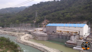
Barrage: Harnessing Water’s Power and Environmental Impact

It’s the structure that is responsible for increasing the height of the watercourse and diverting the water into the river intake and further to power intake through which it could be transported to turbines through the tunnel.
The construction of the barrage required the diversion and de-watering of the vicinity wherein the construction was to be done. For serving this motive, the principal watercourse became diverted through a channel. To accomplish that, a coffer dam become created from Boulders and muck received from excavation.
Table of Contents
COMPONENTS OF BARRAGE
Mainly the Barrage is composed of two abutments and 4 piers joined together via breast walls. The piers and abutment have the provision of stop log gates on the upstream side and radial gates on the downstream side.
The top of the barrage has a provision of a Gantry device whose most important cause for existence is to manipulate the gate openings. The trunnion component at the downstream aspect of the barrage has the principal purpose of wearing the weight coming from the gate assembly. The structure is similarly prolonged through training walls and wing walls on both aspects of the banks. The purpose of walls is to present directions to the watercourse coming undiverted via the gates. The Barrage is given support via joining it to the hard strata on each aspect. For this purpose, a drift is constructed.
The cut-off wall is made to prevent the seepage of water from the upstream to the downstream side. adjoining the cut-off wall, NOF (Non-Overflow phase) is provided to attach the deck slab of the barrage to the drift.
While construction of the barrage, the excavation for drift was done about 17m on the left side and 23m on the right side.
CONSTRUCTION OF BARRAGE:
Diversion and de-watering of water: To make the conditions to be suitable for construction in a flowing river, it was necessary to divert and de-water the area. To serve this purpose, Coffer dam was constructed which was made of boulders and muck. Dam proficiently confined the flow of water for approximately the first half width of the river to the second half of the river so that the construction could be done in the first half. The coffer dam was designed to sustain the discharge of up to 200 cumecs.
Excavation: The excavation had to be done in such a manner so that the whole structure remains stable, not only for maximum flow conditions. For this reason, it was necessary that the excavation should be done to such an extent that a hard stratum is achieved.
Plain cement concrete (P.C.C): Filling up with P.C.C for the excavated portion provides a strong bond between the hard strata and the foundation, which ensures structural stability. In the barrage, reinforcement details were provided only for a depth of 3m beneath the river bed level. So, the 7m of depth was filled with PCC. The provision of P.C.C creates a seepage-free condition inside the excavated area and provides a hard and leveled surface for concreting.
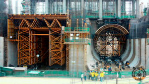
Reinforcement and shuttering: Shuttering is the process of defining the boundaries of a structure for concreting purposes using plywood. Firstly, the formwork is erected and then the reinforcement is tied. Reinforcement of company SAIL TMT of grade Fe500 is used for the construction of the barrage.
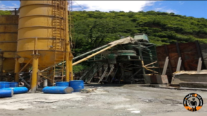
Concreting: For concreting purposes, majorly M20A40 grade concrete was used for the super-structure and a layer of thickness 750 mm of High-Performance Concrete (HPC) was also used.M60 was also used in the basement of the barrage. High-Performance concrete is nothing but the concrete formed by using the extra amount of cement in it.
SPECIFICATIONS OF BARRAGE:
| Location | Kund Village |
| Average River Bed Level | 998.50m |
| Elevation of top | 1020.00m |
| Full Reservoir Level (FRL) | 1017.00m |
| Maximum Draw down Level (MDDL) | 1008.50m |
| Maximum Drawdown Level (MDDL) | 59m |
| No. of Bays | 5 |
| No. of Abutments | 2 |
| No. of Piers | 4 |
| Pier thickness | 3.5 m |
| Abutment thickness | 2.5m |
| Width of each bay | 8m |
| Barrage Discharge Capacity | 5700 m^3/s. |
WORKING OF BARRAGE:
As stated above, the purpose of the barrage is to divert the watercourse to the intake structure. This will be achieved by regulating the opening of gates so as to allow the diversion discharge of only 59.6 cumecs.
Two types of gates are installed on the barrage. They are:
1. Stop log
2. Gate Radial Gate
Stop log Gate: These are the gates that are constructed on the upstream side of the barrage. The main intending purpose of providing stop log gates is for the maintenance of radial gates which are responsible for the diversion of the water. The radial shape provides an extra surface area to the flowing water, hence less pressure will be exerted on gates resulting in less damage. The opening of the gate will be controlled by a gantry machine installed on the top of the barrage. The gate assembly will have heavy-duty wires which will be connected to the gantry machine.

Radial Gates: These are the main gates on the downstream side that serve the purpose of storing and regulating water and it helps in diverting water to the intake.

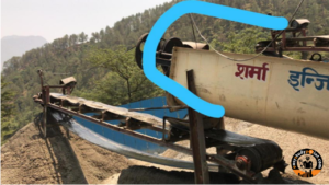
Epoxy treatment:
It is given for the protection and maintenance of the concrete bay walls. During the 2013 disaster in the Mandakini River, the barrage was heavily affected. So In order to fill up the cracks V-shaped chipping is done for protection against scouring.
Concrete Apron:
It is provided in a barrage in order to prevent scouring. It also serves the function to hold the sand compacted and densified between two sheet piles in order to increase the bearing capacity when the barrage floor is designed as a raft.
ENVIRONMENTAL RELEASE PIPE:
Water released from a barrage into a river downstream is known as an environmental flow.. Environmental flows can help to:
- Protect aquatic ecosystems and reduce aquatic weeds and the frequency of
algal blooms - Improve river health
As per the Indian govt. Rules, it is mandatory to release 18% of the total water into the river.

FOUNDATION GALLERY: It is a gallery that is constructed below the river bed. It is constructed for the purpose of inspecting and checking the seepage of the water. Grouting is done in order to fill the cracks.
Barrage vs Dam
| Barrage | Dam |
| An example of a hydraulic construction used to control a river’s flow and store water for irrigation, drinking water, or other uses is a barrage. Water is diverted and the upstream water level is managed by a barrage in order to provide a steady and controlled supply downstream. Barricades are generally constructed in places like estuaries or tidal rivers where the difference between high and low tides is large. | To hold water and form a reservoir, a dam is a sizable wall built over a river or a valley. A dam’s main function is to store water for use in a variety of applications, including flood control, hydropower generation, irrigation, and water delivery. Dams, as opposed to barrages, are often found in non-tidal river basins. |
| To avoid seawater intrusion during high tides, buildings are frequently constructed close to the sea | intended to retain a large volume of water, forming a deep reservoir. |
| Navigation locks that permit the passing of ships and boats may be present. | The water that has been held can be released as needed to supply water or produce electricity further downstream. |
| When compared to a dam reservoir, the reservoir built behind the barrage is often smaller. | By utilizing the power of water flowing via turbines, dams may produce hydropower. |
| includes gates or sluices to control the water level and the flow of the water. | Additionally, they can aid in controlling downstream flow during dry spells and avoiding floods during heavy downpours. |
Recommended Books on Barrages and Water Management
Dams and Development:- https://amzn.to/4ikxXqE
Water Resources Engineering:- https://amzn.to/3QGRpC9
Hydrology and Hydraulic Systems:- https://amzn.to/4bwsgDW


Post Comment