Design Example of One-Way Slab (IS 456:2000)
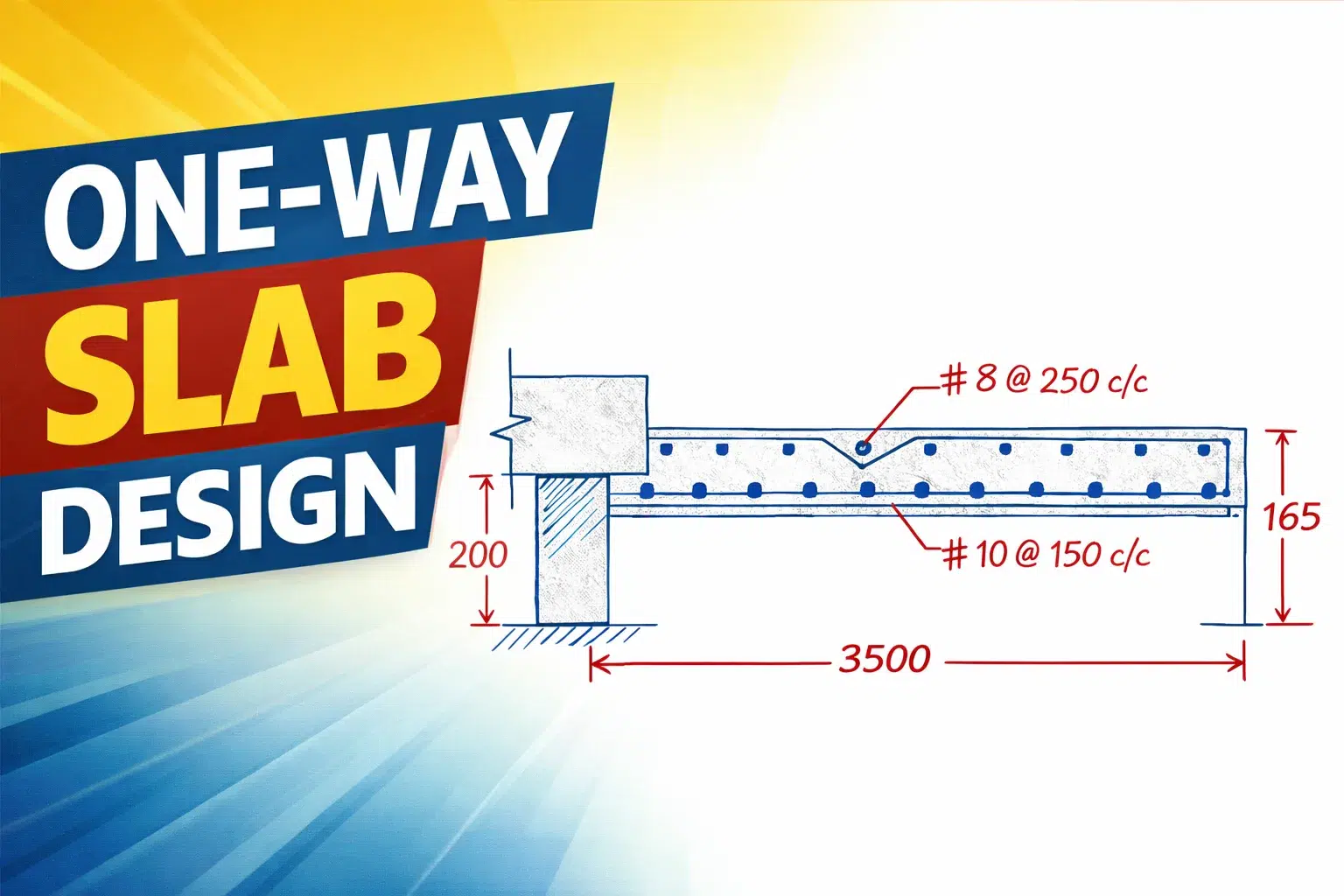
Table of Contents
Design Example of One-Way Slab (IS 456:2000)
A slab is one of the most important structural elements in reinforced concrete buildings. It transfers loads from floors to beams and columns.
When the length of the slab is more than twice the shorter span, the slab mainly bends in one direction. Such slabs are called one-way slabs.
In this article, we will learn the step-by-step design of a one-way slab according to IS 456:2000 using a practical example.
This example will help civil engineering students and site engineers understand the complete slab design process including depth calculation, load calculation, bending moment, reinforcement design, shear check, and deflection check.
Step-by-Step One Way Slab Design
Step 1: Given Data
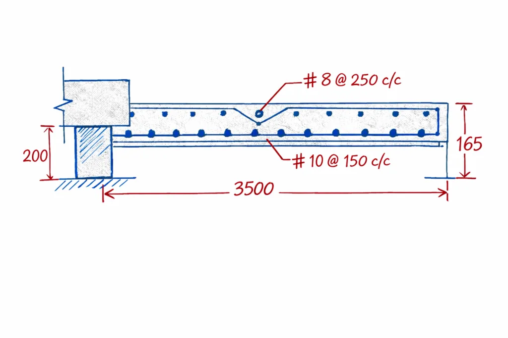
Clear span = 3.5 m
Width of supports = 200 mm
Concrete grade = M20
Steel grade = Fe415
Live load = 4 kN/m²
Floor finish = 1 kN/m²
Step 2: Depth of Slab
Effective depth is assumed using span/depth ratio. Assuming clear cover = 20 mm
Overall depth
Step 3: Effective Span
Effective span is the smaller of the following values:
- Clear span + effective depth
- Centre to centre distance of supports
Step 4: Load Calculation
Self weight of slab Floor finishLive loadTotal service loadUltimate load
Step 5: Bending Moment
For simply supported slab
Step 6: Check Limiting Moment
Mu,lim=0.138fckbd2 Mu,lim=54kN−m
SinceMu<Mu,lim
The section is under-reinforced.
Step 7: Main Reinforcement
Required steel areaAst=524mm2
Provide
10 mm diameter bars @ 150 mm c/c
Step 8: Distribution Reinforcement
Minimum steelProvide
8 mm diameter bars @ 250 mm c/c
Step 9: Shear Check
Shear stressPermissible shear stressSinceThe slab is safe in shear.
Step 10: Deflection Check
Actual ratio(L/d)=26
SinceThe slab satisfies deflection criteria.
Final Reinforcement
Main reinforcement
10 mm bars @ 150 mm c/c
Distribution reinforcement
8 mm bars @ 250 mm c/c
Overall slab thickness
165 mm
IS Code References
The following clauses of IS 456:2000 are used in slab design:
- Clause 23.2 – Deflection control
- Clause 26.5 – Minimum reinforcement
- Table 19 – Shear strength of concrete
- Clause 22 – Bending moment calculation
- SP-16 design tables for reinforcement
The design of a one-way slab involves several important steps such as calculating loads, determining slab thickness, checking bending moment, designing reinforcement, and verifying shear and deflection criteria.
By following the procedures given in IS 456:2000, engineers can design safe and efficient slab structures.
Understanding this design process is essential for civil engineering students, structural engineers, and site engineers working on reinforced concrete structures.
- Creep of Concrete: Definition, Mechanisms, Effects & Long-Term Deflection Explained:- https://engineerlatest.com/creep-of-concrete-explained/#google_vignette
- Shrinkage in Concrete: Types, Causes, Effects & Design Considerations Explained:– https://engineerlatest.com/shrinkage-in-concrete-types-effects-design/
- The Arch bridges and Cantilever Bridges:- https://engineerlatest.com/the-arch-bridges-and-cantilever-bridges/
- Steel Bridges Types and Benefits:- https://engineerlatest.com/steel-bridges-types-and-benefits/
- Truss Bridges, Types, Design Benefits, and Components Overview:- https://engineerlatest.com/truss-bridges-types-design-benefits-and-components-overview/
- Footings and Foundations Explained: Types, Functions, and IS 456 Guidelines:- https://engineerlatest.com/footings-and-foundations-explained/
- Differences Between IS 1893:2016 and IS 1893:2025 for Earthquake Resistant Design:- https://engineerlatest.com/differences-between-is-18932016-and-is-18932025-for-earthquake-resistant-design/


1 comment