Wind Load Calculation for PEB Building as per IS 875(Part 3):2015
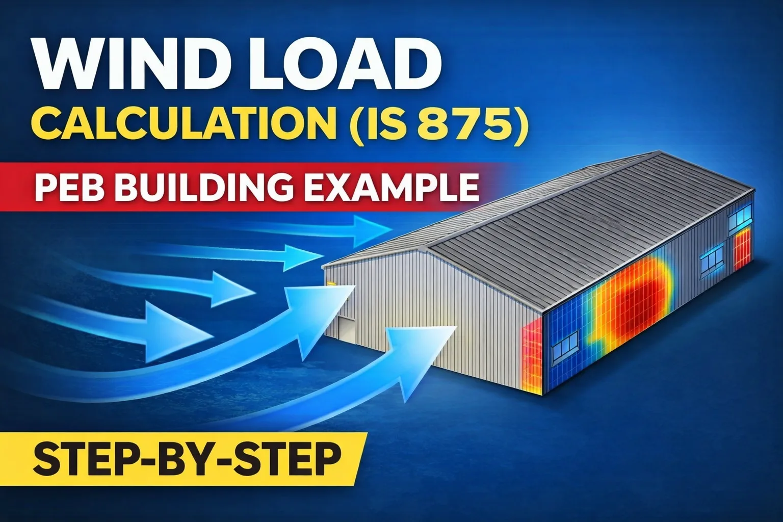
Table of Contents
Wind load is one of the most critical forces acting on steel structures, especially Pre-Engineered Buildings (PEB). Proper estimation of wind pressure ensures structural safety, serviceability, and economy.
In this article, we will explain a example of wind load calculation for a PEB building at Noida, using IS 875 (Part 3): 2015.
This guide is especially useful for:
- Structural engineers
- ETABS/STAAD users
- Civil engineering students

Project Details
The project involves the design of a PEB industrial-type structure with the following parameters:
- Location: Noida
- Basic Wind Speed: 47 m/s
- Building Length: 26 m
- Building Width: 20 m
- Eave Height: 5 m
- Roof Type: Pitched roof
- Roof Angle: 5.71°
- No. of Bays: 4
Types of Loads Considered
1. Dead Load (DL)
Dead load includes self-weight of structure and permanent components.
- Roof Load: 20 kg/m²
- Main Frame: 1.26 kN/m
- End Wall: 0.63 kN/m
2. Live Load (LL)
Live load represents temporary loads like maintenance or workers.
- Roof Live Load: 57.5 kg/m²
- Main Frame: 3.58 kN/m
- End Wall: 1.79 kN/m
3. Collateral Load (CL)
Includes services like ducts, lighting, and piping.
- Roof Collateral Load: 25 kg/m²
- Main Frame: 1.57 kN/m
- End Wall: 0.78 kN/m
4. Other Loads
- Solar Load: 0
- Mezzanine Load: 0
Step-by-Step Wind Load Calculation (IS 875:2015)
Step 1: Basic Wind Speed (Vb)
From IS 875 wind map:
Step 2: Wind Speed Factors
According to IS 875:
- k₁ (Probability Factor) = 1.0
- k₂ (Terrain Factor) = Category 2
- k₃ (Topography Factor) = 1.0
- k₄ (Cyclonic Factor) = 1.0
Step 3: Design Wind Speed (Vz)
Step 4: Wind Pressure (Pz)
Step 5: Design Wind Pressure
Considering reduction factors:
- Area Averaging Factor = 0.9
- Combination Factor = 0.9
- Directionality Factor = 0.9
Final:Pressure Coefficients
Internal Pressure Coefficient (Cpi)
- Building Type: Enclosed
- Value:
External Pressure Coefficient (Cpe)
From IS 875 (Part-3) Table-5 External Pressure Coefficients For Walls of Rectangular Clad Buildings.
| Wind Angle | coff. for wall | coff. for wall | coff. for wall | coff. for wall |
| 0 degree | 0.70 | -0.20 | -0.50 | -0.50 |
| 90 degree | -0.50 | -0.50 | -0.70 | -0.20 |
For 0 degree
Walls
| Cpe | P.d | Bay length | Middle Panel =(P.dxbay length) | End Panel (P.dxbay length/2) | |
| A | 0.9 | 0.873 | 6.275 | 2.7453 | 5.4906 |
| B | -0.4 | -0.388 | 6.275 | -1.21735 | -2.4347 |
| C | -0.7 | -0.679 | 6.275 | -2.4347 | -4.2607 |
| D | -0.7 | -0.679 | 6.275 | -2.1303 | -4.2607 |
- Left Wall: +0.70
- Right Wall: -0.20
- Windward Wall: -0.50
- Leeward Wall: -0.50
For 90 degree
Walls
| Cpe | P.d | Bay length | Middle Panel =(P.dxbay length) | End Panel (P.dxbay length/2) | |
| A | -0.7 | -0.679 | 6.275 | -2.1303 | -4.260 |
| B | -0.7 | -0.679 | 6.275 | -2.1303 | 4.260 |
| C | +0.9 | +0.873 | 6.275 | 2.7390 | 5.478 |
| D | -0.4 | -0.388 | 6.275 | -1.21735 | -2.4347 |
From IS 875 (Part-3) Table-6 External Pressure Coefficients For Pitched Roofs of Rectangular Clad Buildings. By interpolrate our angle is 5.17
| Wind Angle | coff. for Roof | coff. for wall |
| 0 degree | -0.943 | -0.4 |
| 90 degree | -0.8 | -0.43 |
For 0 degree, fist we take Roof (-0.2)
| Cpe | p.d | Middle Panel=(P.dxbay length) | End Panel (P.dxbay length/2) |
| -0.949 | -1.1058 | -3.4694 | -6.938 |
| -0.4 | -0.582 | -1.826 | -3.652 |
For 90 degree, fist we take Roof (-0.2)
| Cpe | p.d | Middle Panel=(P.dxbay length) | End Panel =(P.dxbay length/2) |
| -1 | -0.97 | -6.086 | -3.433 |
| -0.63 | -0.611 | -3.834 | -1.917 |
For 0 degree, fist we take Roof (0.2)
| Cpe | p.d | Middle Panel=(P.dxbay length) | End Panel (P.dxbay length/2) |
| -0.74 | -0.717 | -4.499 | -2.2495 |
| -0.2 | -0.194 | -1.217 | -0.6086 |
For 90 degree, fist we take Roof (0.2)
| Cpe | p.d | Middle Panel=(P.dxbay length) | End Panel =(P.dxbay length/2) |
| -0.6 | -0.582 | -3.652 | -1.826 |
| -0.23 | -0.223 | -1.3993 | -0.699 |
Final Wind Load Application
Wind load is calculated using:Where:
- A = area of surface
- = design wind pressure
Now appling wind load forces to PEB Building
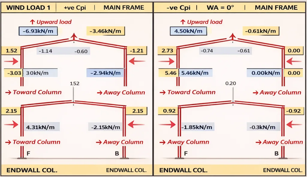


Wind Load Calculation
- Creep of Concrete: Definition, Mechanisms, Effects & Long-Term Deflection Explained:- https://engineerlatest.com/creep-of-concrete-explained/#google_vignette
- Shrinkage in Concrete: Types, Causes, Effects & Design Considerations Explained:– https://engineerlatest.com/shrinkage-in-concrete-types-effects-design/
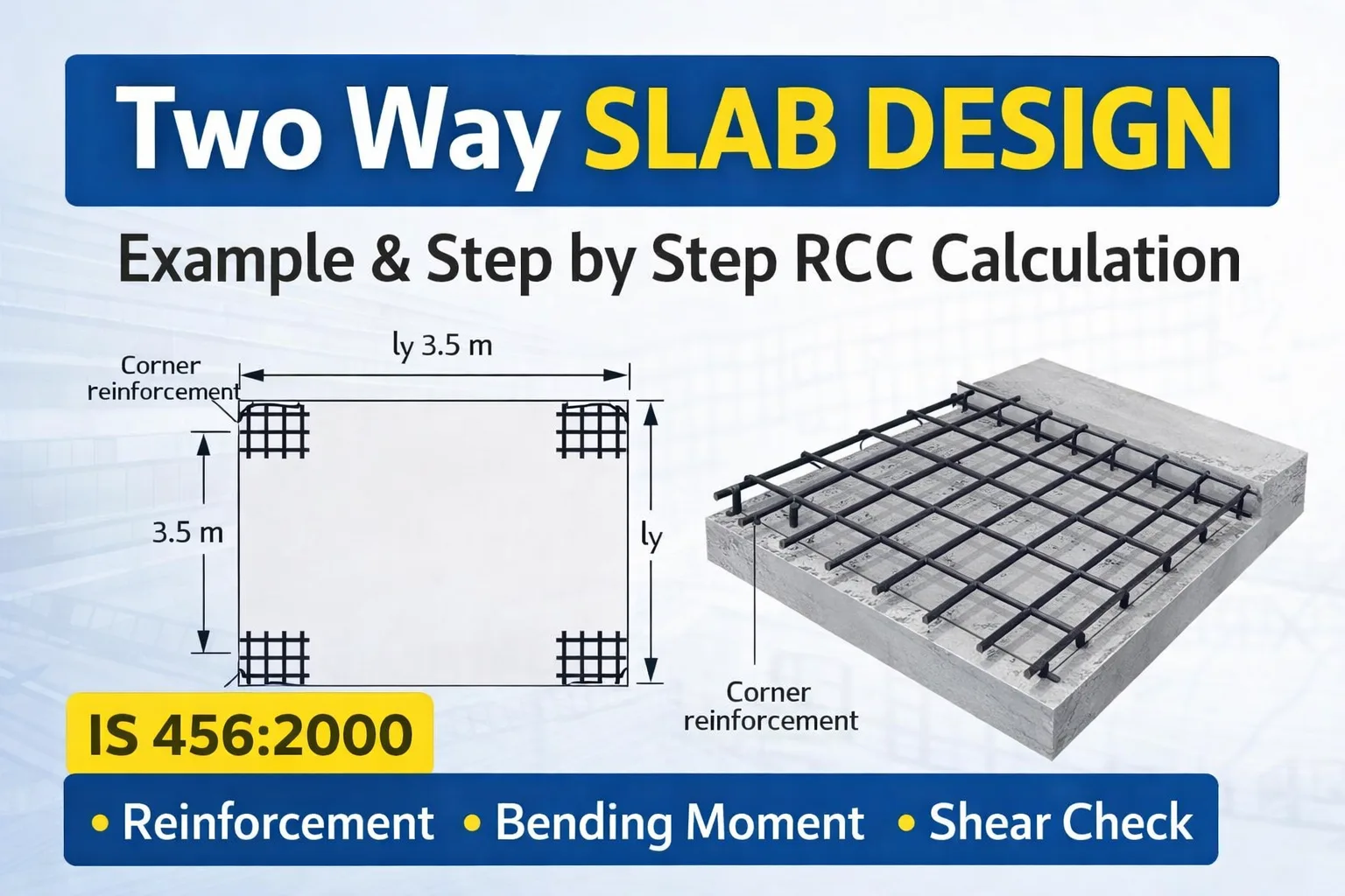
- Two-Way Slab Design Example (IS 456:2000) – Step-by-Step Explanation:- https://engineerlatest.com/two-way-slab-design-example-is-4562000/
- Steel Bridges Types and Benefits:- https://engineerlatest.com/steel-bridges-types-and-benefits/
- Truss Bridges, Types, Design Benefits, and Components Overview:- https://engineerlatest.com/truss-bridges-types-design-benefits-and-components-overview/
- Footings and Foundations Explained: Types, Functions, and IS 456 Guidelines:- https://engineerlatest.com/footings-and-foundations-explained/
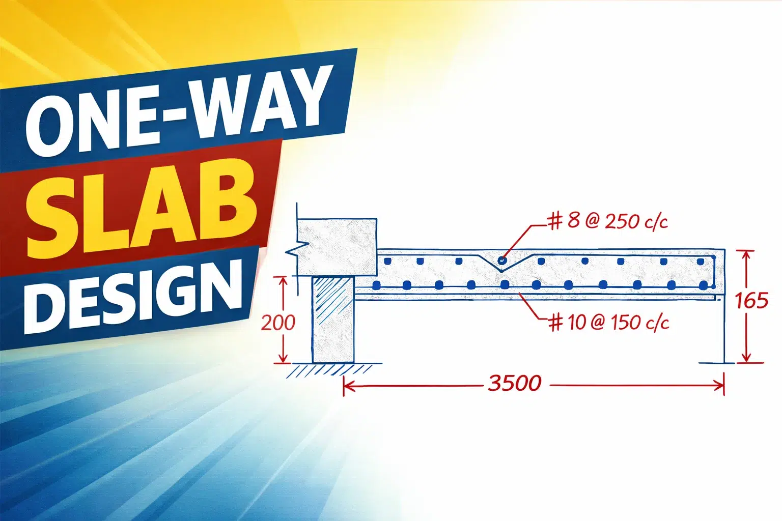
- Design Example of One-Way Slab (IS 456:2000):- https://engineerlatest.com/design-example-of-one-way-slab-is-4562000/



Post Comment